

Introduction to Linear Motion Track Systems
Fundamental Principles of Linear Motion
Cable or belt-driven systems that convert rotary motion to linear motion through traction Screw-based systems (lead screws, ball screws) that translate rotary motion to linear motion through threaded engagement Cam and follower mechanisms that transform rotational motion into linear motion through profiled contact Linear motors that produce direct linear motion through electromagnetic forces Rack and pinion systems where gear teeth engage to convert rotation to linear movement
Core Components of Linear Motion Track Systems
1. Linear Bearings and Guides
Plain linear bearings use sliding contact between surfaces, often with lubrication to reduce friction. While simpler and more cost-effective, they typically have higher friction coefficients and require more maintenance. Rolling element bearings incorporate balls or rollers between the moving and stationary parts, significantly reducing friction. Common types include: Linear ball bearings using recirculating ball elements for smooth motion Linear roller bearings with cylindrical rollers for higher load capacity Angular contact bearings for combined radial and axial load support
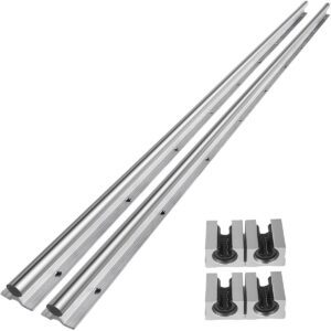
Profiled rail guides (also called linear rail guides) offer exceptional precision and rigidity. These systems consist of: Rail (the fixed track with precisely ground raceways) Carriage (the moving component with matching raceways and bearing elements)
Profiled rail guides are categorized by their rail cross-section, with common types including: Square rail guides (offering high rigidity and precision) Round rail guides (providing more flexibility and easier installation) Compact rail guides (combining small size with good load capacity)
2. Linear Motion Shafts and Support Systems
Precision ground shafts offer exact dimensional tolerances and surface finishes for high-performance applications Chromed shafts provide enhanced wear resistance and corrosion protection Aluminum or composite shafts offer lighter weight alternatives for specific applications
Linear bearings or bushings support the shaft at regular intervals Shaft supports or hangers mount to the frame and contain the bearing elements End supports anchor the shaft ends while accommodating thermal expansion
3. Drive Mechanisms
Ball screws and lead screws convert rotary motion to precise linear motion through threaded engagement: Ball screws use recirculating ball bearings between the screw and nut for high efficiency and load capacity Lead screws rely on sliding friction, offering simpler construction and self-locking capability
Belt drives use toothed or v-belts with pulleys for high-speed, long-distance linear motion: Timing belts with metal or polymer teeth provide precise synchronization V-belts offer high-speed capability with proper tensioning
Linear motors produce direct linear motion through electromagnetic interaction: Iron core linear motors provide high force density Ironless linear motors offer lower inertia and better heat dissipation Voice coil motors deliver precise, rapid short-stroke movements
Rack and pinion systems use gear engagement for robust, high-force linear motion
4. Motion Control Components
Position sensors provide feedback on the moving element’s location: Linear encoders offer direct position measurement with high resolution Potentiometers provide cost-effective position sensing Magnetostrictive sensors measure position without contact
Limit switches define the operational boundaries of motion Home position sensors establish a reference point for system calibration Motion controllers interpret sensor feedback and adjust drive signals to achieve desired motion profiles
5. Structural Components and Framing
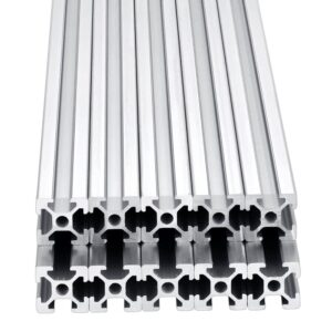
Linear rail systems integrate rails, carriages, and support structures Aluminum extrusions offer lightweight, modular framing solutions Steel frames provide maximum rigidity for heavy-duty applications Mounting brackets and accessories facilitate component installation and alignment
Types of Linear Motion Track Systems
1. Linear Guide Systems
Monorail systems feature a single rail with one or more carriages for compact applications Dual rail systems use parallel rails with multiple carriages for increased load capacity and rigidity Overhung load designs accommodate cantilevered loads with specialized carriage configurations
2. Ball Screw and Lead Screw Systems
Ball screw systems use recirculating ball bearings between the screw and nut for: High efficiency (typically 90% or more) Precise positioning (repeatability to ±0.005 mm possible) High load capacity (up to several tons) Moderate to high speed operation
Lead screw systems rely on sliding friction between the screw and nut for: Self-locking capability (no backdriving under load) Lower cost implementation Quiet operation Suitable for vertical applications where holding position is critical

3. Belt-Driven Linear Systems
Toothed belt systems (timing belts) provide: High-speed capability (up to 10 m/s) Precise positioning (with encoder feedback) Long travel lengths (up to 12 meters or more) Lightweight construction
V-belt systems offer: High-speed operation Smooth operation with proper tensioning Cost-effective solution for non-precision applications
4. Linear Motor Systems
Iron core linear motors provide: High force density (suitable for heavy loads) Good heat dissipation through iron core Cost-effective solution for many industrial applications
Ironless linear motors offer: Lower inertia and better dynamic response Reduced cogging and smoother motion Excellent heat dissipation properties Suitable for high-precision applications
Voice coil motors deliver: Extremely precise, rapid short-stroke movements Low moving mass Fast response times Common in optical and scientific instrumentation
5. Cam-Driven and Linkage Systems
Cam-follower systems convert rotary motion to linear motion through profiled contact Linkage mechanisms use geometric arrangements to produce linear motion from rotary input Rack and pinion systems provide robust linear motion through gear engagement
Applications of Linear Motion Track Systems
1. Industrial Automation and Manufacturing
CNC machining centers use multi-axis linear motion systems for precise tool movement Pick-and-place machines in electronics assembly rely on high-speed linear stages Material handling systems employ conveyor belts with integrated linear motion components Robotic arms use linear actuators for precise positioning Automated inspection systems depend on stable linear motion for consistent measurements
2. Medical and Laboratory Equipment
Medical imaging systems (CT scanners, MRI machines) use linear stages for precise patient positioning Surgical robots require sub-micron positioning accuracy for minimally invasive procedures Laboratory automation (DNA sequencers, liquid handlers) depends on reliable linear motion Diagnostic equipment (blood analyzers, microscopy systems) uses linear stages for sample positioning Rehabilitation devices employ linear motion for controlled therapeutic movement
3. Semiconductor and Electronics Manufacturing
Wafer handling requires ultra-clean, high-precision linear motion with nanometer-level positioning Photolithography equipment uses air-bearing linear stages for extreme precision Chip testing systems depend on stable linear motion for reliable electrical characterization Packaging and assembly equipment uses linear motion for micro-scale component placement Inspection systems (optical, electron beam) require stable linear motion for defect detection
Air or magnetic bearings for frictionless movement Vacuum compatibility Temperature compensation Anti-vibration mounting
4. 3D Printing and Additive Manufacturing
Cartesian 3D printers use three orthogonal linear axes (X, Y, Z) for material deposition Delta robots employ parallel linear motion arms for high-speed printing Large-format 3D printers use linear rail systems for stable, long-range movement Multi-material printers require synchronized linear motion for precise material placement
High positional accuracy (±0.05 mm or better) Smooth motion to prevent layer artifacts Thermal stability to minimize expansion effects Reliable operation over long print durations
5. Consumer Products and Appliances
Office equipment (printers, copiers, scanners) use linear motion for paper handling Automotive systems (power seats, sunroofs, mirrors) employ compact linear actuators Home appliances (dishwashers, washing machines) use linear motion for door mechanisms Furniture (adjustable desks, ergonomic chairs) use linear actuators for position adjustment Entertainment systems (projectors, TVs) use linear motion for positioning
Compact size and lightweight construction Quiet operation Cost-effectiveness Long service life with minimal maintenance
Selection Criteria for Linear Motion Systems
1. Load Requirements
Static load capacity (maximum load without motion) Dynamic load capacity (load during movement) Moment loads (torque around X, Y, Z axes) Load distribution (centered, offset, cantilevered)
2. Precision and Repeatability Needs
Standard applications (±0.1 mm tolerance) Precision applications (±0.01 mm tolerance) Ultra-precision applications (±0.001 mm or better)
Guide rail manufacturing tolerances Bearing preload and clearance Thermal expansion effects Backlash in drive systems
3. Travel Distance and Speed Requirements
Short-stroke applications (a few millimeters to centimeters) Medium travel (several hundred millimeters) Long travel (several meters)
Maximum operational velocity Acceleration/deceleration rates Duty cycle (percentage of time in motion) Impact of travel length on speed capabilities
4. Environmental Conditions
Temperature extremes (requiring special materials or lubricants) Cleanroom environments (needing contamination-free components) Harsh or corrosive environments (demanding stainless steel or protective coatings) Vibratory or shock-prone environments (requiring enhanced rigidity)
Sealed or protected bearings Corrosion-resistant materials Temperature compensation mechanisms Dust-proof or waterproof enclosures
5. Maintenance and Service Life
Lubrication needs (oil, grease, or maintenance-free designs) Wear characteristics (expected component lifespan) Accessibility for maintenance Environmental sealing requirements
Installation and Alignment Best Practices
1. Pre-Installation Preparation
Verify component compatibility (ensure all parts match specifications) Inspect components for damage (check for shipping or handling issues) Prepare the installation area (clean, level, and accessible workspace) Gather proper tools and equipment (including precision measuring instruments)
2. Frame and Base Preparation
Ensure adequate rigidity (the frame must resist deflection under load) Achieve proper flatness (typically within 0.1 mm/m for most applications) Maintain cleanliness (remove all contaminants that could affect alignment) Provide adequate support (avoid overhangs that could cause vibration)
3. Rail Installation
Mount rails parallel (within specified tolerance, typically 0.02-0.05 mm/m) Maintain correct spacing (based on carriage design and load requirements) Use appropriate fasteners (with proper torque specifications) Follow manufacturer’s alignment procedures (often using gauge blocks or laser alignment tools)
Pre-loaded rail mounting kits Laser alignment systems Dial indicators for precise measurement
4. Carriage and Drive System Installation
Mount carriages securely (following manufacturer’s guidelines) Install drive system components (screws, belts, motors) with proper alignment Adjust belt tension or screw pre-load (to specified values) Verify free movement (without binding or excessive friction)
Coupling alignment (between motor and drive system) Belt tracking (for belt-driven systems) Screw support bearings (for lead screw systems)
5. Final Alignment and Testing
Systematic alignment verification (checking all axes and planes) Initial movement testing (verifying smooth operation at low speed) Load testing (gradually applying operational loads) Performance validation (checking against specified accuracy and repeatability)
Maintenance and Troubleshooting
1. Routine Maintenance Procedures
Lubrication (applying appropriate lubricants at specified intervals) Inspection (checking for wear, damage, or contamination) Cleaning (removing debris and contaminants) Tightening (checking and adjusting fastener torques) Alignment verification (periodic checks for maintaining precision)
Operating hours Environmental conditions Load characteristics Manufacturer recommendations
2. Common Maintenance Tasks
Linear bearing maintenance (checking preload, lubrication, wear patterns) Screw and nut maintenance (cleaning, lubrication, backlash checks) Belt inspection (looking for wear, fraying, proper tension) Motor and drive maintenance (checking connections, cooling, performance) Sensor calibration (verifying position feedback accuracy)
3. Troubleshooting Common Issues
Excessive noise or vibration (may indicate misalignment, wear, or improper lubrication) Binding or erratic movement (could result from contamination, misalignment, or worn components) Positioning inaccuracies (often related to backlash, wear, or sensor issues) Premature wear (typically caused by contamination, overload, or improper lubrication) Overheating (may indicate excessive friction, inadequate lubrication, or drive issues)
Future Trends in Linear Motion Technology
1. Smart and Connected Systems
Predictive maintenance (monitoring wear and performance in real-time) Adaptive control (adjusting parameters based on operating conditions) Digital twins (virtual models for simulation and optimization) Remote monitoring and diagnostics (enabling proactive maintenance)
2. High-Precision and Nanopositioning Technologies
Sub-nanometer positioning (for semiconductor and research applications) Active vibration isolation (minimizing environmental effects) Thermal compensation systems (maintaining precision despite temperature changes) Advanced materials (with superior dimensional stability)
3. Energy Efficiency and Sustainability
Low-friction materials and designs (reducing energy consumption) Regenerative braking systems (recovering energy in deceleration) Lightweight components (reducing inertia and power requirements) Eco-friendly lubricants and materials (minimizing environmental impact)

4. Integrated Motion Solutions
Pre-configured motion subsystems (reducing design and installation time) Modular designs (enabling flexible configuration for different applications) Customized solutions (tailored to specific application requirements) Simplified maintenance (with standardized components and interfaces)
5. Advanced Materials and Manufacturing Techniques
Lighter, stronger components (using composites and advanced alloys) Additive manufacturing (creating complex geometries for improved performance) Surface treatment innovations (enhancing wear resistance and durability) Precision fabrication techniques (achieving tighter tolerances)
Conclusion
