

Introduction to Linear Roller Bearings
Fundamental Principles of Linear Roller Bearings
Cylindrical rolling elementsthat travel along precisely machined raceways A carriage assemblythat maintains proper spacing and alignment of the rollers A guide railthat serves as the reference path for linear motion A retention systemthat keeps rollers properly positioned and spaced
Higher load capacitydue to increased contact area Greater rigidityunder load conditions Improved stabilityfor precision applications Reduced deflectionunder heavy loads Enhanced moment load resistance
Types of Linear Roller Bearings
1. Cylindrical Roller Bearings
High load capacityin radial directions Excellent rigidityunder load Good for heavy-duty applications Moderate speed capabilities
Single-row cylindrical roller bearings(for standard applications) Double-row cylindrical roller bearings(for increased load capacity) Multi-row cylindrical roller bearings(for extreme load conditions) Precision cylindrical roller bearings(for high-accuracy requirements)
2. Needle Roller Bearings
Compact designwith high load capacity Excellent for space-constrained applications High rigidityin limited space Good for oscillating movements
Drawn cup needle roller bearings(for compact installations) Precision needle roller bearings(for high-accuracy applications) Needle roller thrust bearings(for axial load applications) Combined needle roller bearings(for combined load directions)
3. Cam Follower Roller Bearings
Integrated stud or yoke designs Excellent for oscillating or reciprocating motion High load capacity in specific orientations Good for cam-driven systems
Stud-type cam followers(for standard applications) Yoke-type cam followers(for alternate mounting configurations) Thrust cam followers(for axial load applications) Insulated cam followers(for electrical isolation)
4. Crossed Roller Bearings
Extremely high rigidityand precision Equal load capacity in all directions Compact designwith high performance Excellent for precision positioning
Precision stages and tables Robot joints and wrists Precision measuring equipment High-precision automation
5. Tapered Roller Bearings
Ability to handle both radial and axial loads Excellent for combined load conditions Good for thrust applications High load capacity in multiple directions
Machine tool spindles Gearboxes and power transmission Heavy-duty automation Aerospace applications
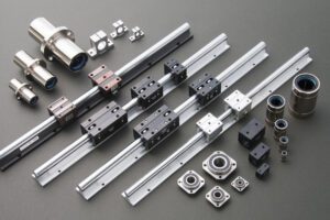
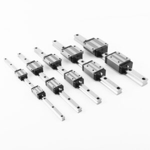
Components of Linear Roller Bearing Systems
1. Guide Rails
Precision-machined raceways(ground to exacting tolerances) Various cross-sectional profiles(square, profiled, or specialized) Different materials(typically hardened steel, sometimes stainless or ceramic-coated) Multiple mounting options(flanged, base-mounted, etc.)
High rigidityto maintain precision under load Excellent surface finishfor reduced friction Thermal stabilityto minimize expansion effects Load distribution featuresfor optimized performance
2. Carriages (Blocks)
Precision-machined pocketsfor rollers Various sizes and load capacities Different mounting configurations(for attachments and payloads) Multiple roller arrangements(for different load directions)
Optimized internal geometryfor smooth roller contact High-quality sealing systemsfor contamination protection Precision-matched componentsfor consistent performance Various preload optionsfor performance tuning
3. Rolling Elements (Rollers)
Straight cylindrical rollers(for standard applications) Tapered rollers(for combined load applications) Needle rollers(for compact applications) Cam follower rollers(for specialized applications)
Precision-machined to exacting tolerances High-quality materials(chrome steel, stainless steel, or ceramic) Proper hardness and surface finish Optimized length and diameter for specific loads
4. Retainers (Cages)
Prevent roller contact(reducing friction and wear) Maintain proper load distribution Various materials(steel, brass, polymer, etc.) Different designs(for different roller configurations)
Minimal frictionto enhance efficiency Durabilityto withstand operational conditions Proper clearancefor reliable operation Appropriate material selectionfor the application
5. Preload Mechanisms
Zero clearance or slight preloadfor optimal performance Different preload levels(light, medium, heavy) Affects stiffness, accuracy, and friction Customizable for specific application requirements
Improved rigidityfor precise positioning Reduced deflectionunder load Enhanced accuracy and repeatability Optimized performance characteristics
Materials and Construction
1. Rail and Carriage Materials
Hardened alloy steel(most common, offering excellent wear resistance) Stainless steel(for corrosive environments) Ceramic-coated or treated surfaces(for specialized applications) Precision heat treatment(for optimal hardness and durability)
2. Roller Materials
Chrome steel (AISI 52100)(most common, offering excellent hardness and wear resistance) Stainless steel(for corrosive or clean environments) Ceramic (silicon nitride)(for high-speed, high-temperature, or non-magnetic applications) Specialized alloys(for specific performance requirements)
3. Retainer Materials
Steel(for strength and durability) Brass(for good wear resistance and quiet operation) Polymer/plastic(for low-friction, lightweight, or high-temperature applications) Composite materials(for specialized applications)
4. Surface Treatments and Coatings
Hard chrome plating(for enhanced wear resistance) Nitriding or other surface hardening processes(for improved durability) Corrosion-resistant coatings(for harsh environments) Dry lubricant coatings(for maintenance-free operation)
Key Performance Characteristics
1. Load Capacity
Dynamic load capacity(maximum load during motion) Static load capacity(maximum load without motion) Moment load capacity(resistance to tipping forces) Load ratingsvary widely based on size, design, and materials
2. Precision and Tolerance
Accuracy grades(from standard to micron-level precision) Repeatability(ability to return to the same position) Straightness, flatness, and parallelismof components ABEC or similar ratingsfor bearing precision
3. Speed and Acceleration
Maximum allowable speed(based on size, lubrication, and design) Acceleration capabilities(for dynamic applications) DN factor(bearing bore diameter × rpm) indicating speed limitations Critical speed considerationsfor long travel applications
4. Stiffness and Rigidity
System stiffness(resistance to deflection under load) Preload effectson rigidity Rail and carriage designaffecting overall stiffness Mounting considerationsimpacting system rigidity
5. Life Expectancy
L10 bearing life(the number of revolutions at which 90% of bearings will still be operational) Travel lifeestimates based on load and speed Maintenance intervalsand relubrication requirements Environmental factorsaffecting component life
Applications of Linear Roller Bearings
1. Heavy-Duty Machine Tools
CNC milling machinesand machining centersfor heavy cutting operations Grinding machinesand lapping equipment Presses and stamping machines Heavy-duty woodworking machinery
2. Industrial Automation and Manufacturing
Automated assembly linesfor heavy components Material handling equipmentfor large parts Roboticsfor heavy payload applications Automated guided vehicles (AGVs)for heavy transport
3. Aerospace and Defense
Aircraft assembly equipmentfor large components Missile guidance systemsrequiring high rigidity Spacecraft positioning equipment Defense manufacturing machinery
4. Automotive Manufacturing
Body shop equipmentfor large panel handling Powertrain manufacturing machinery Automated welding systemsfor large assemblies Vehicle testing equipment
5. Heavy Equipment and Construction Machinery
Machine tool basesand heavy equipment frames Construction automation systems Mining equipment components Heavy-duty material handling
Selection Criteria for Linear Roller Bearings
1. Load Requirements
Magnitude and direction of loads(radial, axial, or moment loads) Static vs. dynamic loading conditions Load distribution(even or concentrated) Expected shock or impact loads
2. Precision and Accuracy Needs
Required positioning accuracy(microns to millimeters) Repeatability requirements Application tolerance specifications System stiffness needs

3. Travel Distance and Speed Requirements
Required travel length Maximum operational velocity Acceleration/deceleration rates Duty cycle(percentage of time in motion)
4. Environmental Conditions
Temperature rangeand thermal considerations Exposure to contaminants(dust, moisture, chemicals) Corrosive or hygienic environment requirements Vacuum or special atmospheric conditions
5. Maintenance and Service Life
Lubrication requirementsand maintenance intervals Expected service lifeand operating hours Environmental sealing needs Replacement and spare parts availability
Installation and Alignment Best Practices
1. Pre-Installation Preparation
Verify component compatibility(ensure all parts match specifications) Inspect components for damage(check for shipping or handling issues) Prepare the installation area(clean, level, and accessible workspace) Gather proper tools and equipment(including precision measuring instruments)
2. Rail Installation
Mount rails parallel(within specified tolerance, typically 0.02-0.05 mm/m) Maintain correct spacing(based on carriage design and load requirements) Use appropriate fasteners(with proper torque specifications) Follow manufacturer’s alignment procedures(often using gauge blocks or laser alignment tools)
3. Carriage and Drive System Installation
Mount carriages securely(following manufacturer’s guidelines) Install drive system components(belts, screws, motors) with proper alignment Adjust belt tension or screw pre-load(to specified values) Verify free movement(without binding or excessive friction)
4. Final Alignment and Testing
Systematic alignment verification(checking all axes and planes) Initial movement testing(verifying smooth operation at low speed) Load testing(gradually applying operational loads) Performance validation(checking against specified accuracy and repeatability)
Maintenance and Troubleshooting
1. Routine Maintenance Procedures
Lubrication(applying appropriate lubricants at specified intervals) Inspection(checking for wear, damage, or contamination) Cleaning(removing debris and contaminants) Tightening(checking and adjusting fastener torques) Alignment verification(periodic checks for maintaining precision)
2. Common Maintenance Tasks
Roller inspection(checking for wear, damage, or contamination) Seal and retainer inspection(checking for wear or damage) Fastener inspection(checking for proper torque and tightness) Carriage and rail inspection(checking for wear, damage, or misalignment) Lubrication system maintenance(checking reservoirs, lines, and delivery)
3. Troubleshooting Common Issues
Excessive noise or vibration(may indicate misalignment, wear, or improper lubrication) Binding or erratic movement(could result from contamination, misalignment, or worn components) Positioning inaccuracies(often related to backlash, wear, or sensor issues) Premature wear(typically caused by contamination, overload, or improper lubrication) Overheating(may indicate excessive friction, inadequate lubrication, or drive issues)
Future Trends in Linear Roller Bearing Technology
1. Smart and Connected Systems
Integrated sensorsfor monitoring load, temperature, and vibration Predictive maintenancecapabilities Digital twinsfor simulation and optimization Remote monitoring and diagnostics
2. High-Precision and Nanopositioning Technologies
Sub-micron positioning capabilities Advanced materialsfor enhanced performance Thermal compensation systems Vacuum and cleanroom compatible designs
3. Energy Efficiency and Sustainability
Low-friction materials and designs Regenerative braking concepts Lightweight components Eco-friendly lubricants and materials
4. Integrated Motion Solutions
Pre-configured linear motion modules Modular designs for flexible configuration Customized solutions for specific applications Simplified maintenance and installation
5. Advanced Materials and Manufacturing Techniques
New material developmentsfor enhanced performance Additive manufacturingfor specialized components Precision fabrication techniques Surface treatment innovations
Conclusion
